Rotator module version 2.1
This revision is from 2014/01/21 07:55. You can Restore it.
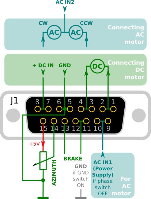
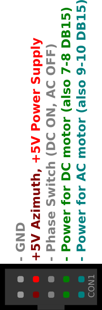
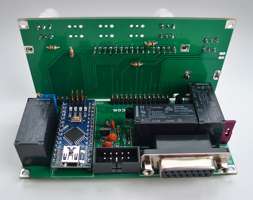
Output to rotator (DB15 female) and power inputs connector
Assembly manual(Edit)
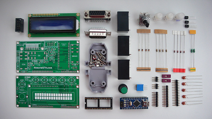
All components
- Solder R5 R6 R7 R8 (marked in blue)
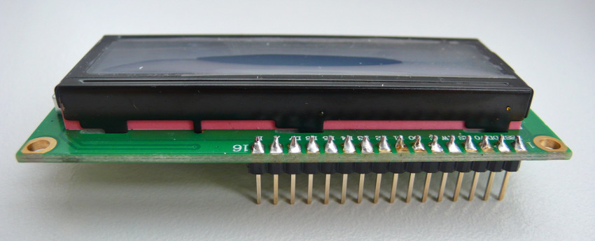
- 16 pins strip to LCD
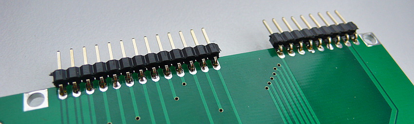
- 13 and 9 pins 90° strip
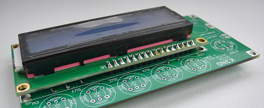
- LCD module to PCB
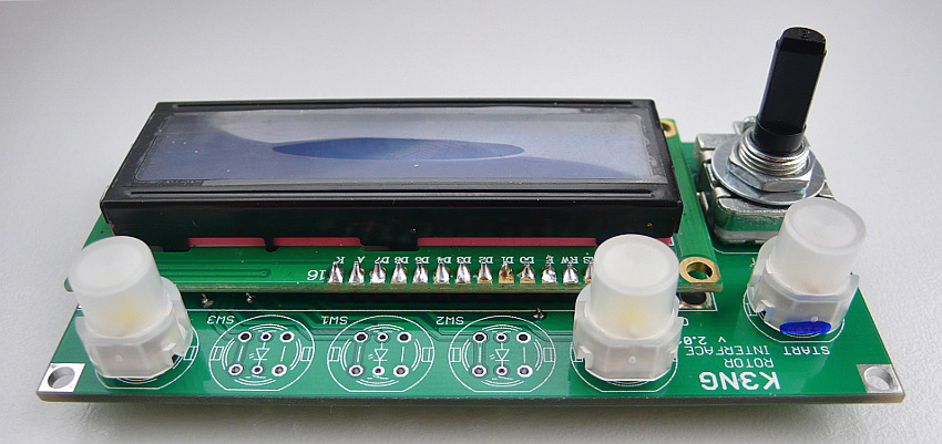
- CW, CCW and START switch (marked in blue) and preset encoder, Now front panel is final
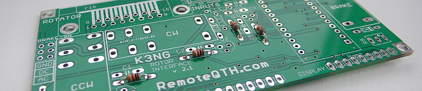
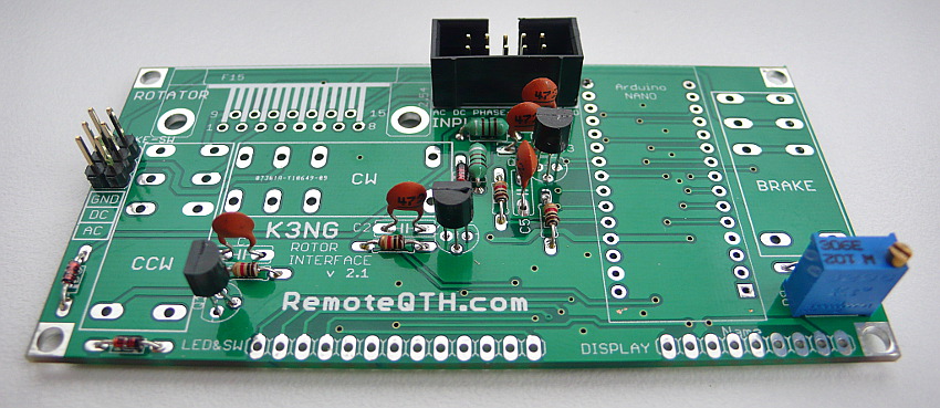
- Next R1 R2 R3 R4 (marked in black) solder on main board
- L1 L2 (marked in green)
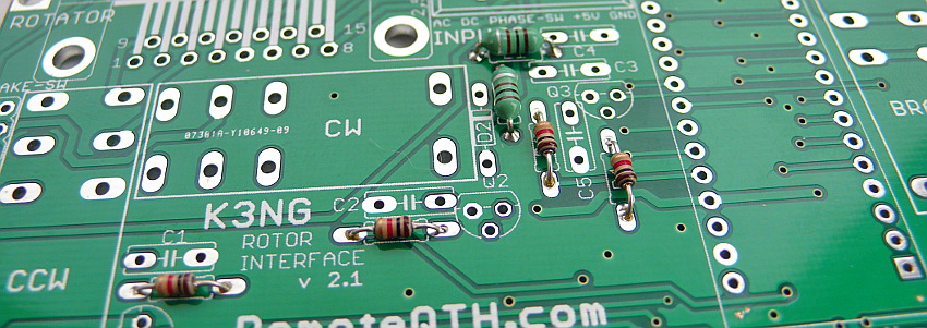
- D1 D2 D3 D4 (marked in red)

- Q1 Q2 Q3
- C1 C2 C3 C4 C5
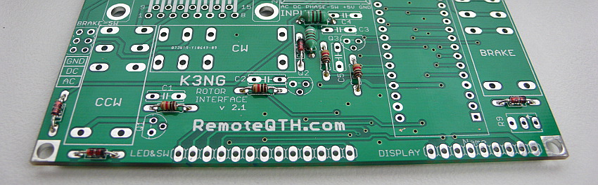
- 6 pins of brake sw, Inputs connector, R9
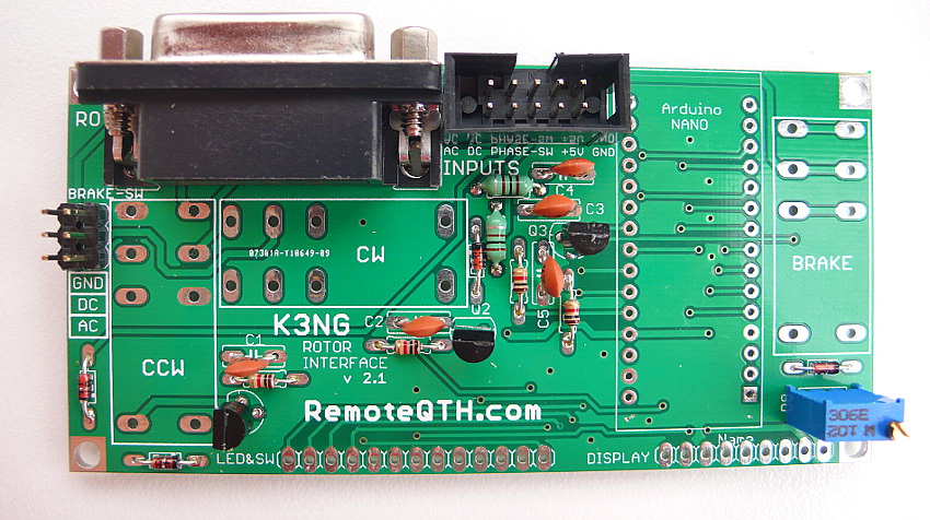
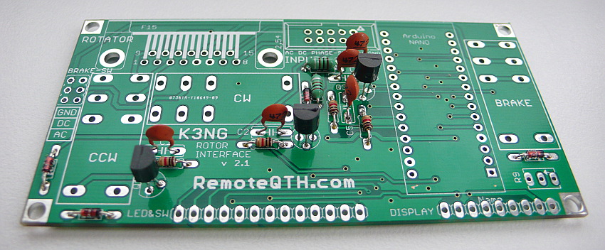
- F15 connector
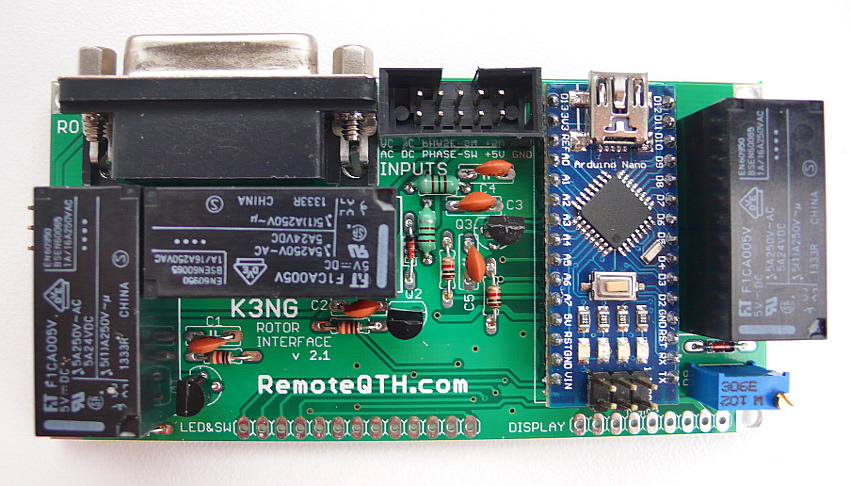
- three relay, Arduino nano
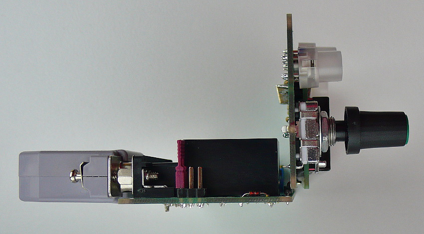

- front panel via pin strip