6x2 Antenna switch control
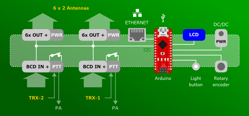
The hardware(Edit)
How to connect Power(Edit)
- Plug DC jack 5,5 outer, 2,1 mm inner size.
- Connect 12-15V DC power voltage. Current dependency to connected antenna switch, alone controller about 60mA.
Front side(Edit)
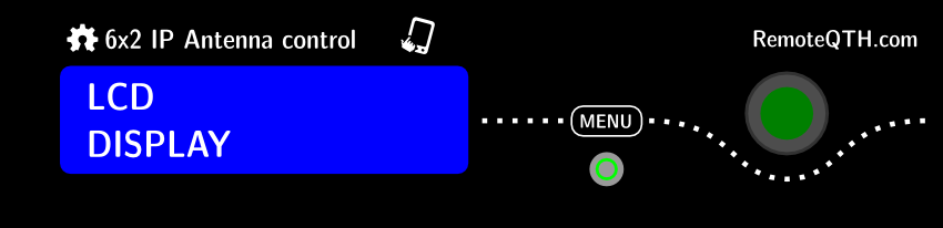
- LCD - shows selected antenna - first line Input/Output 1, second line Input/Output 2
- MENU - light button. For activate press button more than 0,5 second. Green light signals if manual control activate.
- ENCODER - rotary encoder primary move cursor, after activate MENU you can select antenna outputs manual or back activate BCD inputs.
Rear side(Edit)
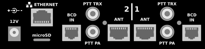
- DC POWER - input jack 5,5/2,1 mm size for DC power between 12-14 Volts. Same Power on pin8 ANT outputs.
- ETHERNET - OPTIONAL module for controlled switch manual over simple web page.
- microSD - not implemented.
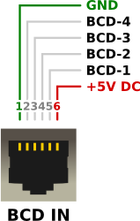
- BCD IN - band data inputs activate two levels, dependency to JP8 jumper
- HIGH - TTL voltage input
- LOW - grounded input (contains own 1k pull up resistor)
- PTT TRX - grounded activate input PTT from transceiver (contains own 1k pull up resistor)
- PTT PA - PTT continues from TRX to this output for power amplifier. If detect collision between inputs band, this output will be deactivate.
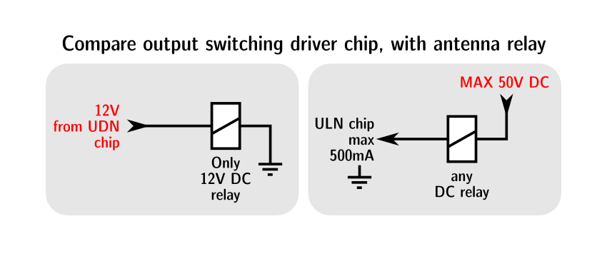
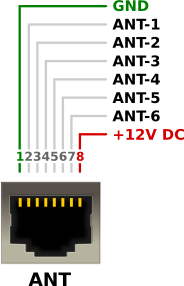
- ANT - six outputs, will be in two levels dependency to preset JP1 and JP2 jumper. Also 12V DC power and ground available.
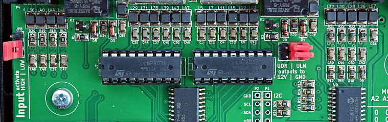
- ULN if use internal driver ULN2803A - open collector 500 mA each outputs
- UDN if use internal source 12V power driver UDN2580A.
Left side(Edit)
- From the left side is accessible USB mini connector from Arduino NANO, which is usable for upload new firmware.
Board preset(Edit)
Before opening has to be removed eight screws
- three on left side
- three on right side
- two on rear side, near double cinch.
LCD contrast(Edit)
- with potentiometer RV1 - near left side LCD module
Inputs BCD Levels(Edit)
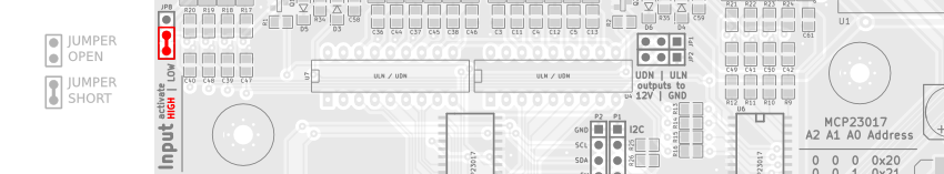
- JP8 to HIGH - activate BCD inputs with TTL signal level (1k ohm pull-down resistor).
- And uncoment line in firmware
#define inputHigh // enable input High level (default)
- JP8 to LOW - activate BCD inputs to ground (1k ohm pull up resistor).
- And coment line in firmware
//#define inputHigh // enable input High level (default)
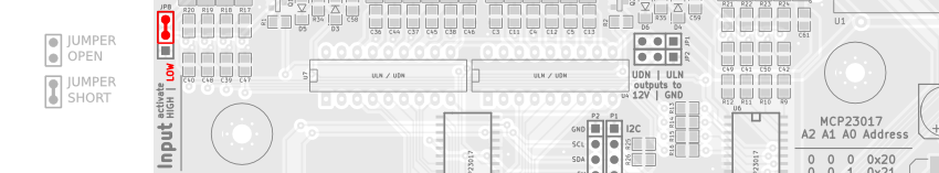
Outputs Antenna switching(Edit)
This jumper must be set dependency to used U4 and U7 IO chip - do not change before change chip!
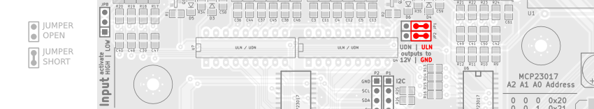
ULN - for ULN2803A open collector driver - switching antenna relay with grounded outputs.
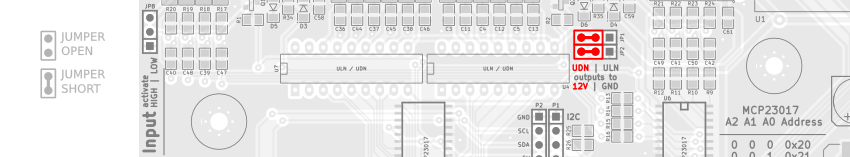
UDN - for UDN2580A source 12V power driver - switching antenna relay with 12V power outputs.
Cable connect(Edit)
- BCD IN - Input band data from TRX 1 or 2
- Antenna outputs - Switched anntenas for TRX 1 or 2
- PTT TRX - input PTT cinch from transceiver (grounding activate).
- PTT PA - output PTT cinch to power amplifier - if controller detect collision, disconnect signal from transceiver PTT.
- 12V - DC Power input (positive center) 12-14V. Same Power on pin8 ANT outputs.
Firmware(Edit)
Upload(Edit)
Band decoder settup is performed via firmware source code. It is compile and upload to device with Arduino GUI.
- For beginners Getting Started with Arduino.
- Connect mini USB connector on left side enclosure.
- Download source code and open in GUI.
- Select menu
- Tools/Board/Arduino nano
- Tools/Procesor/ATmega328
- Tools/Port/<your port>
- If enable Ethernet
- Download ethernet2 library https://github.com/adafruit/Ethernet2
- Find and open file Dhcp.h and replace line
from
  int beginWithDHCP(uint8_t *, unsigned long timeout = 60000, unsigned long responseTimeout = 5000);
to
  int beginWithDHCP(uint8_t *, unsigned long timeout = 6000, unsigned long responseTimeout = 5000);
Configure(Edit)
- Description antennas - show on LCD and web page, firt and last line do not change
char* ant[] = { "All OUT off", // <-- do not change this line "160m Vert.", " 80m Dipole", " 40m Moxon", " 30m Dipole", " 20m 2x 5el", " 10m 4x 6el", "M-off->BCD", // <-- do not change this line }; - Inputs level - changing inputs level also need set JP8 jumper. Before opening enclosure has to be removed eight screws (three on left side, three on right side, two on rear side).
- Set JP8 to HIGH - activate BCD inputs with TTL signal level (1k ohm pull-down resistor). And uncoment line
#define inputHigh // enable input High level (default)
- Set JP8 to LOW - activate BCD inputs to ground (1k ohm pull up resistor). And coment line
//#define inputHigh // enable input High level (default)
- Number of inputs
#define Inputs 6 // number of antenna used
- Number of ports
#define Ports 2 // number of - IN/OUT pair devices and LCD lines (support from 2 to 4)
- LCD culumn
#define LCDculumn 16
- Serial Echo, show status on serial interface
//#define serialECHO       // enable TX echo on serial port
#define SERBAUD    9600    // [baud] Serial port baudrate
- Ethernet - before enable in firmware need open enclosure and instal optional module USR-ES1.
//#define EthModule // enable Ethernet module
- Ethernet addres may be get automatically from DHCP server - for enable uncoment line
#define __USE_DHCP__ // Uncoment to Enable DHCP
- Static IP address (if DHCP disable) set in this lines
IPAddress ip(192, 168, 1, 220);         // IP
IPAddress gateway(192, 168, 1, 200);    // GATE
IPAddress subnet(255, 255, 255, 0);     // MASK
IPAddress myDns(8, 8, 8, 8);            // DNS (google pub)
EthernetServer server(80);              // web server PORT
BCD IN OUT matrix table(Edit)
Set the last two lines (value between 0 to 6) how outputs represent BCD input value.
---------------------------------------------------------------------------------------
Input levels
BCD-1                    0   1   0   1   0   1   0   1   0   1   0   1   0   1   0   1
BCD-2                    0   0   1   1   0   0   1   1   0   0   1   1   0   0   1   1
BCD-3                    0   0   0   0   1   1   1   1   0   0   0   0   1   1   1   1
BCD-4                    0   0   0   0   0   0   0   0   1   1   1   1   1   1   1   1
---------------------------------------------------------------------------------------
Band # input             0   1   2   3   4   5   6   7   8   9  10  11  12  13  14  15
(Yaesu Band)                160 80  40  30  20  17  15  12  10  6m
---------------------------------------------------------------------------------------
                         |   |   |   |   |   |   |   |   |   |   |   |   |   |   |   |
                         V   V   V   V   V   V   V   V   V   V   V   V   V   V   V   V
                    */ { 0,  1,  2,  3,  0,  4,  0,  5,  0,  6,  0,  0,  0,  0,  0,  0 }, /* --> ANT-1 OUTPUT
                    */ { 0,  1,  2,  3,  0,  4,  0,  5,  0,  6,  0,  0,  0,  0,  0,  0 }, /* --> ANT-2 OUTPUT
This example activate non WARC bands.