Band decoder for Arduino
← Web page | HamShop.cz version →
This version is obsolete.
The hardware(Edit)
- Schematics
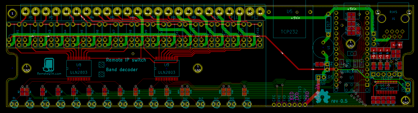
- PCB
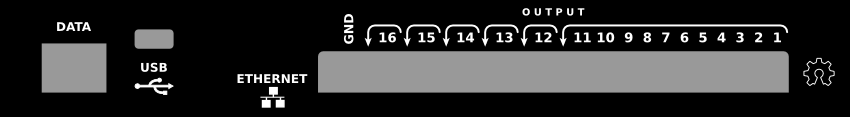
Front side(Edit)

- 1-14 - green LED signalizing relay status.
- 15-16 - not used outputs.
- white square - sign defines the type of equipment.
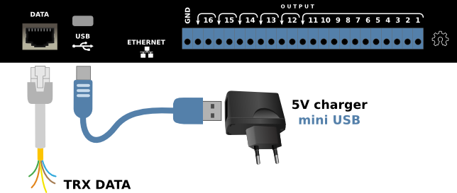
Back side(Edit)
- DATA - RJ45 input data connector for Band decoder
- - TXD (UART/232 dependency internal switch).
- - GND.
- - RXD (UART/232 dependency internal switch).
- - BCD-1 input.
- - BCD-2 input.
- - A/D input.
- - BCD-3 input.
- - BCD-4 input.
- USB - +5V DC POWER supply, or upload arduino firmware.
- ETHERNET - not used.
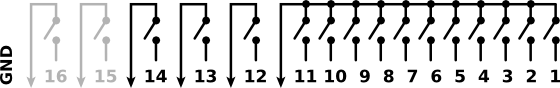
- OUTPUTS - 14 relay outputs and GND.
Configure inputs(Edit)
uncomment and activate only one input in source code
//=====[ Inputs ]=============================================================================================

// #define INPUT_SERIAL   // telnet ascii input - cvs format [band],[freq]\n (serial.h)
// #define ICOM_CIV       // read frequency from CIV (icom_civ.h) ** you must enabled 'CI-V transceive' in TRX settings, and disable ICOM_CIV_OUT **
// #define KENWOOD_PC     // RS232 CAT (kenwood_pc.h)
// #define YAESU_BCD      // TTL BCD in A  (yaesu_bcd.h)
// #define ICOM_ACC       // voltage 0-8V on pin4 ACC(2) connector - need calibrate in (icom_acc.h)
And connect to TRX as described below
Available Inputs
Input Serial(Edit)
Activate uncomment line
#define INPUT_SERIAL
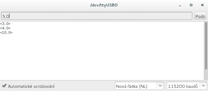
Not need any hardware settings, only send via USB to serial line ascii characters in preconfigured baudrate.
X,YYYYYYY\n
- X - band output in range 0-14, if activate BCD output range is 0-10 because 11-14 reserved for BCD. 0 (zero) = no output will be turned on.
- YYYYYYY - frequency in Hz - has no effect on the output relays, used if any CIV/CAT outputs activated.
- \n - is LF Line Feed (0A in hex)
ICOM CIV(Edit)
Input works in sniff mode (data over one wire - RXD). This means that it is necessary to provide, transmit frequency of TRX to serial line
- enabled CI-V transceive in TRX menu settings
- comunicate with TRX by other device or software (for example logbook with CAT support)
Activate uncomment line
#define ICOM_CIV
Requires baud rate and CIV address in setting section of source code
#define SERBAUD      9600    // [baud] Serial port in/out baudrate
#define CIV_ADRESS   0x56    // HEX Icom adress (0x is prefix)
Deactivate watchdog and request
// #define WATCHDOG       10  // [sec] determines the time, after which the all relays go OFF, if missing next input data - uncomment for the enabled
// #define REQUEST            // use TXD output for sending frequency request (Kenwood PC, Yaesu CAT, Yaesu CAT old, Icom CIV)
In icom_civ.h file you can set rules to select individual output relays, with a resolution of one Hz.
            //=====[ Frequency (Hz) to Band rules ]======================================
            //                                        you can expand rules up to 14 Bands

                 if (freq >=   1810000 && freq <=   2000000 )  {BAND=1;}  // 160m
            else if (freq >=   3500000 && freq <=   3800000 )  {BAND=2;}  //  80m
            else if (freq >=   7000000 && freq <=   7200000 )  {BAND=3;}  //  40m
            else if (freq >=  10100000 && freq <=  10150000 )  {BAND=4;}  //  30m
            else if (freq >=  14000000 && freq <=  14350000 )  {BAND=5;}  //  20m
            else if (freq >=  18068000 && freq <=  18168000 )  {BAND=6;}  //  17m
            else if (freq >=  21000000 && freq <=  21450000 )  {BAND=7;}  //  15m
            else if (freq >=  24890000 && freq <=  24990000 )  {BAND=8;}  //  12m
            else if (freq >=  28000000 && freq <=  29700000 )  {BAND=9;}  //  10m
            else if (freq >=  50000000 && freq <=  52000000 ) {BAND=10;}  //   6m
            else if (freq >= 144000000 && freq <= 146000000 ) {BAND=11;}  //   2m
            else {BAND=0;}                                                // out of range
            //===========================================================================
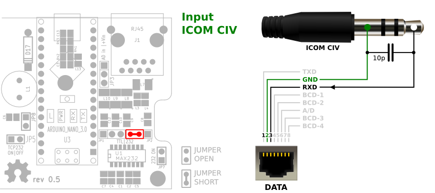
- short JP2 left (RXD)
KENWOOD CAT(Edit)
Input works in sniff mode (data over one wire - RXD). This means that it is necessary to provide, transmit frequency of TRX to serial line
- comunicate TRX with other device or software (for example logbook with CAT support)
- activate function Frequency request which utilizes data output TXD, and prevent the use of any from CAT/CIV output.
Activate uncomment line
#define KENWOOD_PC
Requires baud rate in setting section of source code
#define SERBAUD      9600    // [baud] Serial port in/out baudrate
// #define WATCHDOG       10  // [sec] determines the time, after which the all relays go OFF, if missing next input data - uncomment for the enabled
// #define REQUEST            // use TXD output for sending frequency request (Kenwood PC)
You can also use functions
- WATCHDOG - determines the time, after which the all relay OFF, if missed next input data
- REQUEST - use TXD output for sending frequency request - and prevent the use of any from CAT/CIV output.
In kenwood_pc.h file you can set rules to select individual output relays, with a resolution of one Hz.
        //=====[ Frequency (Hz) to Band rules ]======================================
        //                                        you can expand rules up to 14 Bands

             if (freq >=   1810000 && freq <=   2000000 )  {BAND=1;}  // 160m
        else if (freq >=   3500000 && freq <=   3800000 )  {BAND=2;}  //  80m
        else if (freq >=   7000000 && freq <=   7200000 )  {BAND=3;}  //  40m
        else if (freq >=  10100000 && freq <=  10150000 )  {BAND=4;}  //  30m
        else if (freq >=  14000000 && freq <=  14350000 )  {BAND=5;}  //  20m
        else if (freq >=  18068000 && freq <=  18168000 )  {BAND=6;}  //  17m
        else if (freq >=  21000000 && freq <=  21450000 )  {BAND=7;}  //  15m
        else if (freq >=  24890000 && freq <=  24990000 )  {BAND=8;}  //  12m
        else if (freq >=  28000000 && freq <=  29700000 )  {BAND=9;}  //  10m
        else if (freq >=  50000000 && freq <=  52000000 ) {BAND=10;}  //   6m
        else if (freq >= 144000000 && freq <= 146000000 ) {BAND=11;}  //   2m
        else {BAND=0;}                                                // out of range
        //===========================================================================

- short JP2 right (RXD)
- short JP7 (PWR max232)

- short JP2 right (RXD)
- short JP1 right (TXD)
- short JP7 (PWR max232)
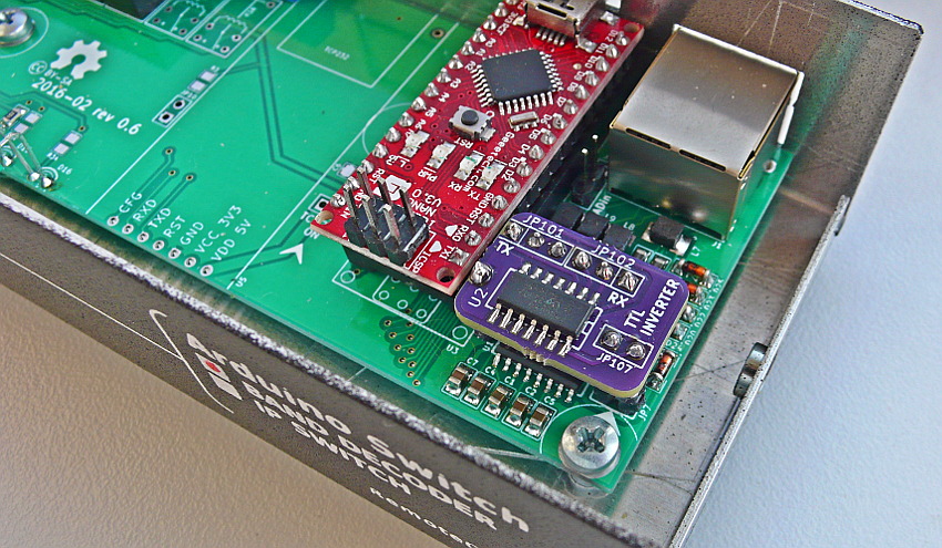
KENWOOD TS-x50 CAT(Edit)
This small PCB inverted TTL signal for old Kenwood RTX.
- compatibile with Band decoder rev. 0.6 or higher
- no more jumper needs
- only plug small add-on to master pcb
- connections to radio by DATA RJ45 connector
YAESU CAT(Edit)
Input worked in sniff mode (data over one wire - RXD). This means that it is necessary to provide, transmit frequency of TRX to serial line
- comunicate TRX with other device or software (for example logbook with CAT support)
- activate function Frequency request which utilizes data output TXD, and prevent the use of any from CAT/CIV output.
Activate uncomment line
#define YAESU_CAT
Requires baud rate in setting section of source code
#define SERBAUD      9600    // [baud] Serial port in/out baudrate
// #define WATCHDOG       10  // [sec] determines the time, after which the all relay OFF, if missed next input data - uncomment for the enabled
// #define REQUEST            // use TXD output for sending frequency request (Kenwood PC, Yaesu CAT)
You can also use functions
- WATCHDOG - determines the time, after which the all relay OFF, if missed next input data
- REQUEST - use TXD output for sending frequency request - and prevent the use of any from CAT/CIV output.
In yaesu_cat.h file you can set rules to select individual output relays, with a resolution of one Hz.
        //=====[ Frequency (Hz) to Band rules ]======================================
        //                                        you can expand rules up to 14 Bands

             if (freq >=   1810000 && freq <=   2000000 )  {BAND=1;}  // 160m
        else if (freq >=   3500000 && freq <=   3800000 )  {BAND=2;}  //  80m
        else if (freq >=   7000000 && freq <=   7200000 )  {BAND=3;}  //  40m
        else if (freq >=  10100000 && freq <=  10150000 )  {BAND=4;}  //  30m
        else if (freq >=  14000000 && freq <=  14350000 )  {BAND=5;}  //  20m
        else if (freq >=  18068000 && freq <=  18168000 )  {BAND=6;}  //  17m
        else if (freq >=  21000000 && freq <=  21450000 )  {BAND=7;}  //  15m
        else if (freq >=  24890000 && freq <=  24990000 )  {BAND=8;}  //  12m
        else if (freq >=  28000000 && freq <=  29700000 )  {BAND=9;}  //  10m
        else if (freq >=  50000000 && freq <=  52000000 ) {BAND=10;}  //   6m
        else {BAND=0;}                                                // out of range
        //===========================================================================
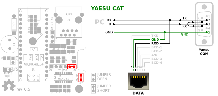
- short JP2 right (RXD)
- short JP7 (PWR max232)

- short JP2 right (RXD)
- short JP1 right (TXD)
- short JP7 (PWR max232)
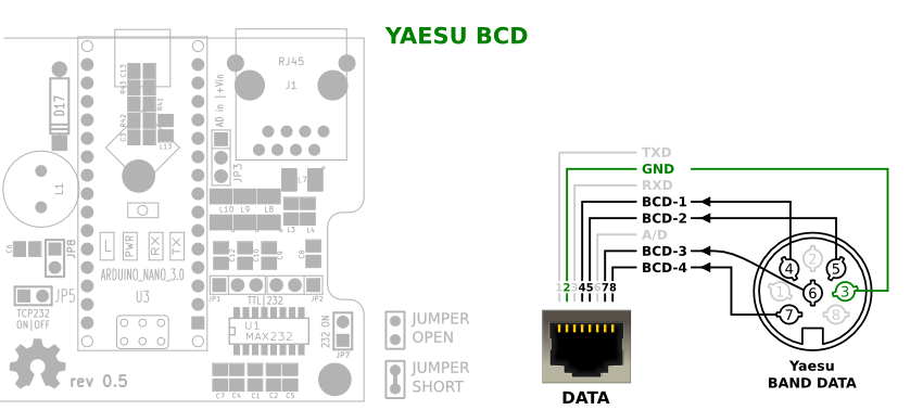
YAESU BCD(Edit)
Activate uncomment line
#define YAESU_BCD
In yaesu_bcd.h file you can set rules to select individual output relays, dependency to BCD input.
=======[ Input BCD ]====================================================================

          BCD 1 --> */ { 0,  1,  0,  1,  0,  1,  0,  1,  0,  1,  0,  1,  0,  1,  0 }, /*
          BCD 2 --> */ { 0,  0,  1,  1,  0,  0,  1,  1,  0,  0,  1,  1,  0,  0,  1 }, /*
          BCD 3 --> */ { 0,  0,  0,  0,  1,  1,  1,  1,  0,  0,  0,  0,  1,  1,  1 }, /*
          BCD 4 --> */ { 0,  0,  0,  0,  0,  0,  0,  0,  1,  1,  1,  1,  1,  1,  1 }, /*
                         |   |   |   |   |   |   |   |   |   |   |   |   |   |   |
                         V   V   V   V   V   V   V   V   V   V   V   V   V   V   V
-------------------------------------------------------------------------------------
Band # in matrix table   0   1   2   3   4   5   6   7   8   9  10  11  12  13  14
Yaesu BCD                   160 80  40  30  20  17  15  12  10  6m  <--- free --->
-------------------------------------------------------------------------------------

========================================================================================
ICOM ACC(2) voltage(Edit)
Activate uncomment line
#define ICOM_ACC
In icom_acc.h file you can set voltage range rules to select individual output relays.
    //=====[ Icom ACC voltage range ]===========================================================

    if (VOLTAGE > 0.73 && VOLTAGE < 1.00 ) {BAND=10;}  //   6m   * * * * * * * * * * * * * * * *
    if (VOLTAGE > 1.00 && VOLTAGE < 1.09 ) {BAND=9;}   //  10m   *           Need              *
    if (VOLTAGE > 1.09 && VOLTAGE < 1.32 ) {BAND=8;}   //  12m   *    calibrated to your       *
    if (VOLTAGE > 1.32 && VOLTAGE < 1.55 ) {BAND=7;}   //  15m   *         own ICOM            *
    if (VOLTAGE > 1.55 && VOLTAGE < 1.77 ) {BAND=6;}   //  17m   *     ----------------        *
    if (VOLTAGE > 1.77 && VOLTAGE < 2.24 ) {BAND=5;}   //  20m   *    (These values have       *
    if (VOLTAGE > 0.10 && VOLTAGE < 0.50 ) {BAND=4;}   //  30m   *   been measured by any)     *
    if (VOLTAGE > 2.24 && VOLTAGE < 2.73 ) {BAND=3;}   //  40m   *          ic-746             *
    if (VOLTAGE > 2.73 && VOLTAGE < 2.99 ) {BAND=2;}   //  80m   *                             *
    if (VOLTAGE > 2.99 && VOLTAGE < 4.00 ) {BAND=1;}   // 160m   * * * * * * * * * * * * * * * *
    if (VOLTAGE > 0.00 && VOLTAGE < 0.10 ) {BAND=0;}   // parking

    //==========================================================================================
When calibrating can read the measured voltage in the terminal, enable the echo function and set serial baudrate
#define SERIAL_echo
#define SERBAUD      9600
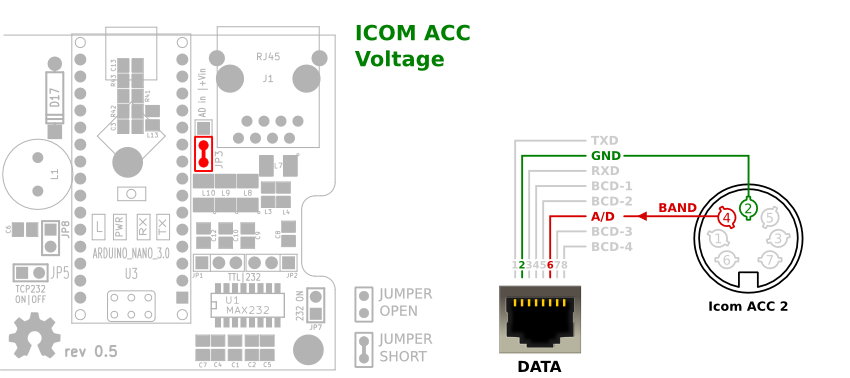
- short JP3
Configure outputs(Edit)
You can uncomment more than one output, but not all combinations are possible. See on Context table and description of parts.
Always usable - may all at once.
- 14 Relay - allways enabled (with enable BCD output, 10 relay)
- Serial echo
- Yaesu BCD
Only one from (not available during active Frequency request option (available only one TXD line)
//=====[ Outputs ]============================================================================================
// #define REMOTE_RELAY         // TCP/IP remote relay - need install and configure TCP232 module
// #define SERIAL_echo          // Feedback on serial line in same baudrate, CVS format <[band],[freq]>\n
// #define ICOM_CIV_OUT         // send frequency to CIV ** you must set TRX CIV_ADRESS, and disable ICOM_CIV **
// #define KENWOOD_PC_OUT       // send frequency to RS232 CAT ** for operation must disable KENWOOD_PC and REQUEST **
// #define BCD_OUT              // output 11-14 relay used as Yaesu BCD
External remote 14 IP Relay(Edit)
Need two device with TCP232 ethernet module included
- IP Band decoder
- IP Relay
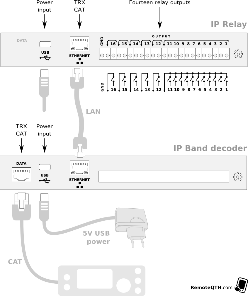
- IP Band decoder use arduino firmware rev 0.4 or higher → for band decoder:
- Remove all jumpers.
- Configure Inputs → dependancy to your trx.
- If band decoder work with you TRX well, activate transceive data with uncomment line
#define REMOTE_RELAY // TCP/IP remote relay - need install and configure TCP232 module
(enable other outputs is not recommended), and upload new firmware (before upload remove all jumpers - after return back). - Enable IP module with short jumper JP5.
- IP Relay - use different arduino firmware for IP relay → band-decoder-0x-rel
- Remove jumper JP5.
- configure three settings
#define delayR   10     //  sec [Relay]         determines the time, after which the relay parking
#define parking  14     //  out [Relay]  1-14   parking output after timeout - optimally for grounded antenna
int baud = 9600;
baudrate must be same as TRX. - Upload firmware.
- Return back jumper JP5.
- Both devices
- Configure Network → baudrate must be same as TRX.
- NOTE: all baudrate must be same
- TRX
- Arduino firmware (band decoder)
- IP module in band decoder
- Arduino firmware (IP relay)
- IP module in IP relay
14 RELAYS(Edit)
- Allways enabled.
An entrance band data, or frequency, converts to output band 0-14 which can be configured in the following table - Preset Band to output matrix - in default settings Band-1 corresponds to Relay-1, etc. You can sets any combination outputs for each band separately. With change zeros and ones in the Matrix table. Band-0 reserved for out of range inputs measure.
//=====[ Sets band -->  to output in MATRIX table ]===========================================================

        boolean matrix[15][15] = { /*

        Band 0 --> */ { 0,  0,  0,  0,  0,  0,  0,  0,  0,  0,  0,  0,  0,  0,  0 }, /*  if inputs out of range
\       Band 1 --> */ { 1,  0,  0,  0,  0,  0,  0,  0,  0,  0,  0,  0,  0,  0,  0 }, /*
 \      Band 2 --> */ { 0,  1,  0,  0,  0,  0,  0,  0,  0,  0,  0,  0,  0,  0,  0 }, /*
  \     Band 3 --> */ { 0,  0,  1,  0,  0,  0,  0,  0,  0,  0,  0,  0,  0,  0,  0 }, /*
   \    Band 4 --> */ { 0,  0,  0,  1,  0,  0,  0,  0,  0,  0,  0,  0,  0,  0,  0 }, /*
    \   Band 5 --> */ { 0,  0,  0,  0,  1,  0,  0,  0,  0,  0,  0,  0,  0,  0,  0 }, /*
     \  Band 6 --> */ { 0,  0,  0,  0,  0,  1,  0,  0,  0,  0,  0,  0,  0,  0,  0 }, /*
IN    ) Band 7 --> */ { 0,  0,  0,  0,  0,  0,  1,  0,  0,  0,  0,  0,  0,  0,  0 }, /*
     /  Band 8 --> */ { 0,  0,  0,  0,  0,  0,  0,  1,  0,  0,  0,  0,  0,  0,  0 }, /*
    /   Band 9 --> */ { 0,  0,  0,  0,  0,  0,  0,  0,  1,  0,  0,  0,  0,  0,  0 }, /*
   /    Band 10 -> */ { 0,  0,  0,  0,  0,  0,  0,  0,  0,  1,  0,  0,  0,  0,  0 }, /*
  /     Band 11 -> */ { 0,  0,  0,  0,  0,  0,  0,  0,  0,  0,  1,  0,  0,  0,  0 }, /*
 /      Band 12 -> */ { 0,  0,  0,  0,  0,  0,  0,  0,  0,  0,  0,  1,  0,  0,  0 }, /*
/       Band 13 -> */ { 0,  0,  0,  0,  0,  0,  0,  0,  0,  0,  0,  0,  1,  0,  0 }, /*
        Band 14 -> */ { 0,  0,  0,  0,  0,  0,  0,  0,  0,  0,  0,  0,  0,  1,  0 }, /*
                        |   |   |   |   |   |   |   |   |   |   |   |   |   |
                        V   V   V   V   V   V   V   V   V   V   V   V   V   V
                     -----------------------------------------------------------
                     |  1   2   3   4   5   6   7   8   9  10  11  12  13  14  |
                     -----------------------------------------------------------
                                          OUTPUTS RELAY*/
        };
//============================================================================================================
Note: if enable BCD output function, relay 11-14 reserved for BCD.
YAESU BCD output(Edit)
Activate uncomment line
#define BCD_OUT
This option will reduce the number of relays at 10. Relay 11-14 used for BCD.
In band-decoder.ino file you can set rules to select BCD output, dependency to detected band input.
//=====[ Output BCD ]==========================================================================
#if defined(BCD_OUT)
    void bcdOut(){
        boolean BCDmatrixOUT[4][11] = { /*
        --------------------------------------------------------------------
        Band # to output relay   0   1   2   3   4   5   6   7   8   9  10
        (Yaesu BCD)                 160 80  40  30  20  17  15  12  10  6m
        --------------------------------------------------------------------
                                 |   |   |   |   |   |   |   |   |   |   |
                                 V   V   V   V   V   V   V   V   V   V   V
                            */ { 0,  1,  0,  1,  0,  1,  0,  1,  0,  1,  0 }, /* --> Relay 11
                            */ { 0,  0,  1,  1,  0,  0,  1,  1,  0,  0,  1 }, /* --> Relay 12
                            */ { 0,  0,  0,  0,  1,  1,  1,  1,  0,  0,  0 }, /* --> Relay 13
                            */ { 0,  0,  0,  0,  0,  0,  0,  0,  1,  1,  1 }, /* --> Relay 14
ICOM CIV output(Edit)
Activate uncomment line
#define ICOM_CIV_OUT
Requires baud rate and CIV address in setting section of source code
#define SERBAUD      9600    // [baud] Serial port in/out baudrate
#define CIV_ADR_OUT  0x56    // HEX Icom adress (0x is prefix)

- short JP1 left (TXD)
KENWOOD CAT output(Edit)
Activate uncomment line
#define KENWOOD_PC_OUT
Requires baud rate in setting section of source code
#define SERBAUD 9600 // [baud] Serial port in/out baudrate

- short JP1 right (TXD)
- short JP7
YAESU CAT output(Edit)
Activate uncomment line
#define YAESU_CAT_OUT
Requires baud rate in setting section of source code
#define SERBAUD 9600 // [baud] Serial port in/out baudrate
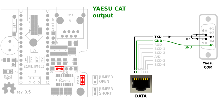
- short JP1 right (TXD)
- short JP7
Upload Firmware(Edit)
Band decoder settup is performed via firmware source code. It is compile and upload to device with Arduino GUI.
- For beginners Getting Started with Arduino.
- Download source code and configuring it.
- Before uploading new firmware you have to
- remove top cover - loosening the two screws on left and right side of the box.
- remove JP1, JP2 and JP7 jumpers
- Select menu
- Tools/Board/Arduino nano
- Tools/Procesor/ATmega328
- Tools/Port/<your port>
- Upload
- After upload set back jumpers dependency to setup.
Have a fun!