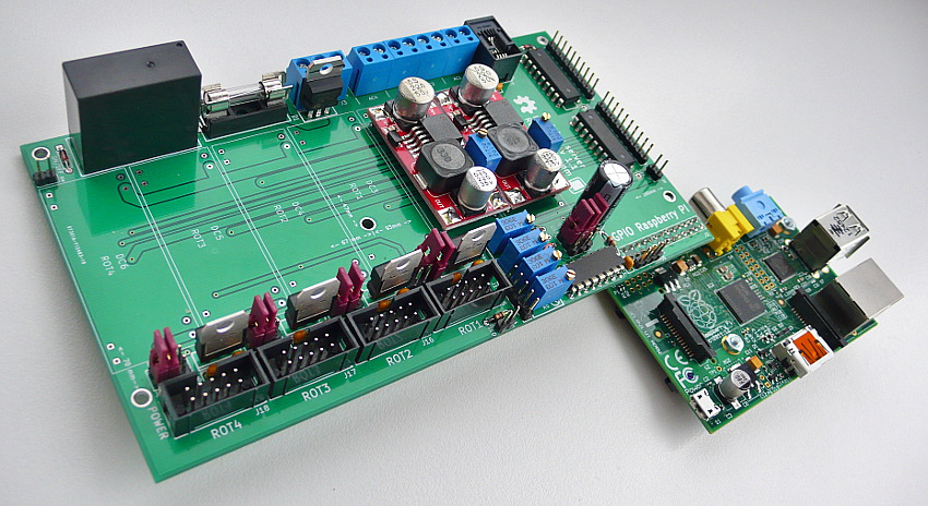
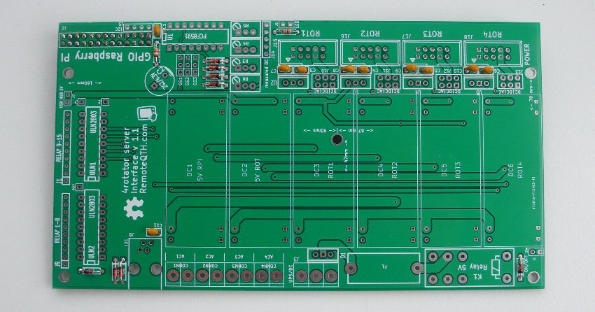
Raspberry PI GPIO interface board
Part list(Edit)
| K1 | Relais |
| U2,U3,U4,U5 | L78M05 |
| D1 | double shotky diode |
| C1,C3,C4,C5,C6,C11 | u1 |
| CONN1, CONN2, CONN3, CONN4 | input terminal |
| D2,D3 | diode |
| D4,D5,D6,D7,D8,D9 | zener diode |
| F1 | fuse |
| GS1, GS2, GS3 | pin array 3x1 |
| J1, J9 | strip 10 pins |
| J2 | pin array 13x2 |
| J3, J4, J6, J7 | array 2 pin |
| J5 | pin array 4x1 |
| J14 | pin array 5x1 |
| J15, J16, J17, J18 | pin array 5x2 |
| R1 | resistor 4k8 |
| R2 | resistor 3k9 |
| R3,R4,R5,R6 | trimmer 10k |
| U1 | A/D PCF8591 |
| ULN1,ULN2 | ULN2803 |
| J10, J11, J12, J13 | pin array 3x2 |
| DC1, DC2, DC3, DC4, DC5, DC6 | DC/DC convertor |
| C7,C8,C9,C10 | capacity u33 |
| C2 | capacity 2G2/6.3V |
| J8 | RJ9 |
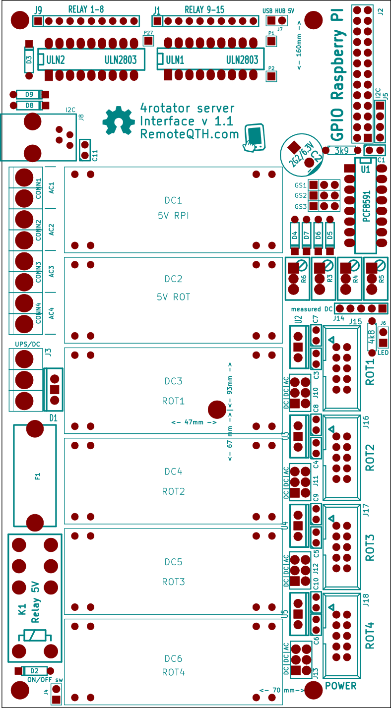
Planting plan(Edit)
Assembly(Edit)
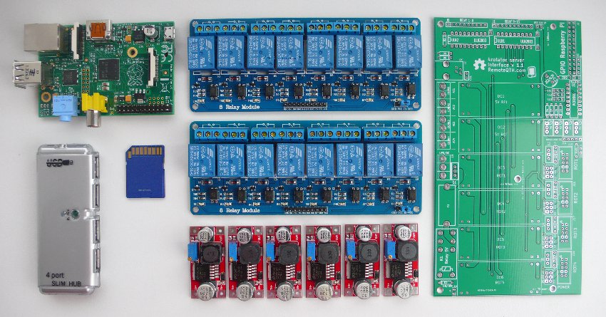

✔ All components
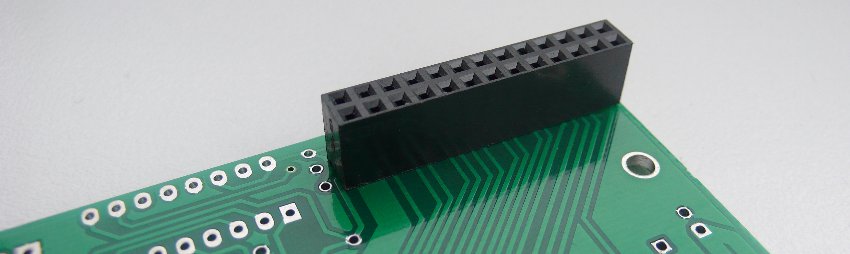
❏ Solder J2 GPIO connector on bottom of pcb - with the exception of pin 17
❏ Next R1 R2, D2 D3 D4 D5 D6 D7 D8 D9 and C1 C3 C4 C5 C6 C11 C7 C8 C9 C10
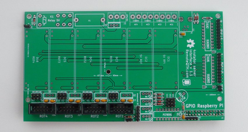
❏ All pin strip and connector J16-19
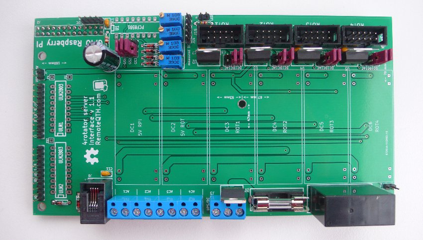
❏ The remaining components - K1, U2 U3 U4 U5, CONN1 CONN2 CONN3 CONN4, F1, R3 R4 R5 R6 - before by soldering turn fully CCW, and put on control screw towards to diodes = center of the potentiometer must be routed to ground, J8
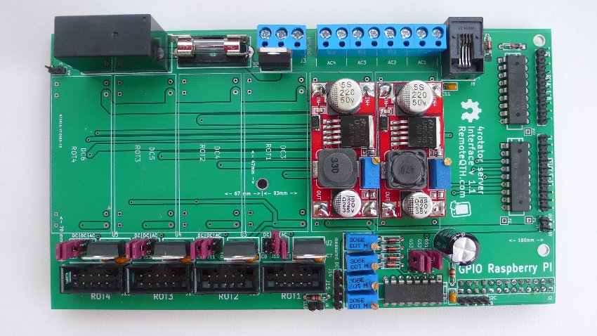
❏ Last IOs U1 ULN1 ULN2 and two mandatory DC/DC converters for Raspberry PI and rotator modules - before mounting must both be set to the output voltage of 5V, otherwise you risk damaging RPI and arduino