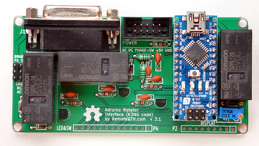
Rotator module version 3.0
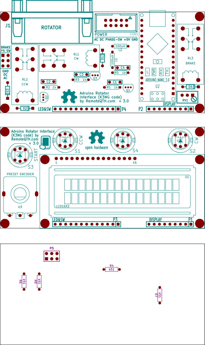
Part list(Edit)
| P1,P2 | strip 9 pins |
| P3,P4 | strip 13 pins |
| P5 | pin array_3x2 |
| R4,R6,R7,R8 | k510 ohm |
| S1,S2,S3 | tact led sw |
| U1 | LCD-16x2 |
| U3 | Preset encoder |
| C1,C2,C3,C4 | capacity 4n7 |
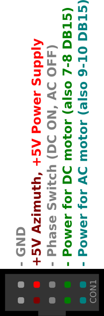
| CON1 | pin array 5x2 |
| D1,D2,D3,D4 | diode 1n4148 |
| J1 | DB15 female connector |
| L1,L2 | inductor 100uH |
| R1,R2,R3,R5 | resistor 1k |
| RV1 | potentiometer 1k |
| U2 | ArduinoNano3.0 |
| P6 | pin_array_3x2 |
| RL1,RL2,RL3 | Relay |
| Q1,Q2,Q3 | transistor BC547 |
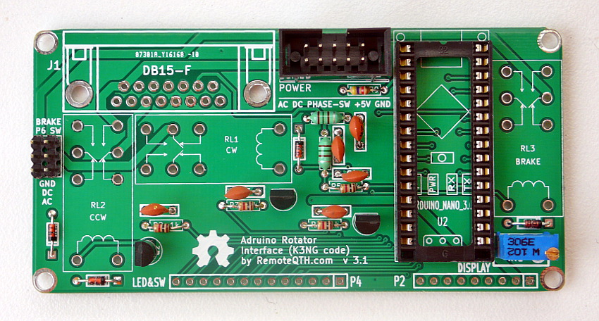
Planting plan(Edit)
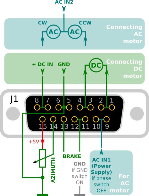
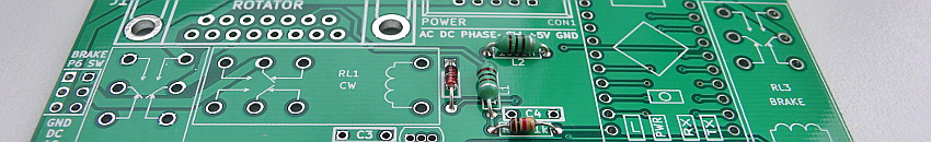
Rotator (DB15 female) and power inputs connector(Edit)
Phase jumper (5+6 CON1) change relay function between DC (change phase voltage) and AC (change direction).
Pin 3 in CON1 - input 5V stabilized voltage from power board This pin may be connected with pin4 CON1, then the voltage measurement uses a common 5V voltage from the power supply module.
The entire module can be powered from USB only, but there is a voltage drop, it is better to use an external source, or a DC/DC converter.
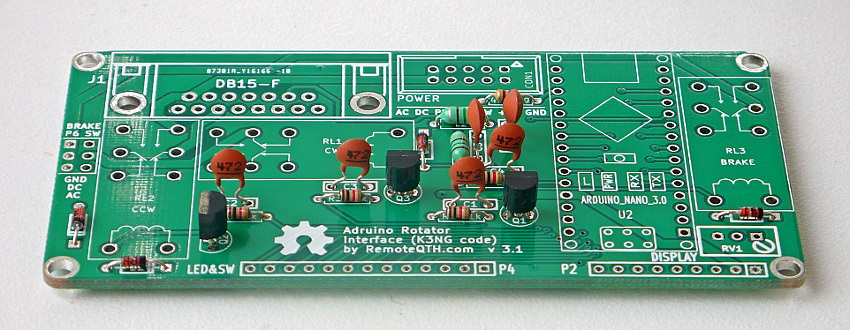
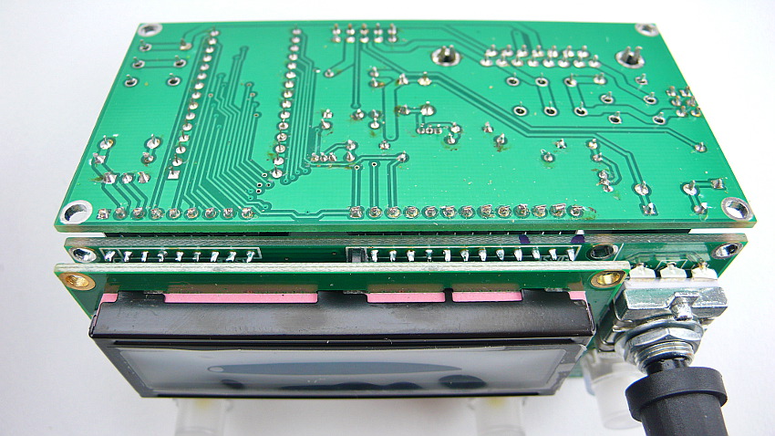
Assembly gallery(Edit)
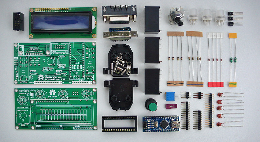
✔ All components
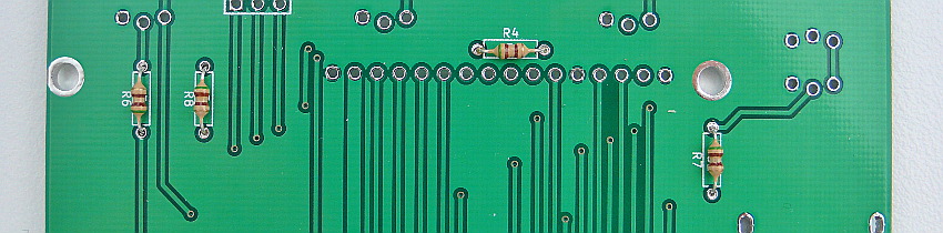
❏ Solder R4 R6 R7 R8 (marked in blue)
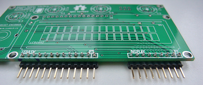
❏ 13 and 9 pins 90° strip
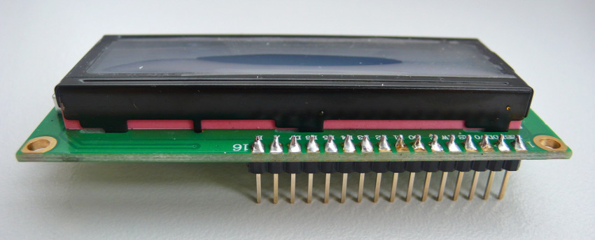
❏ 16 pins strip to LCD
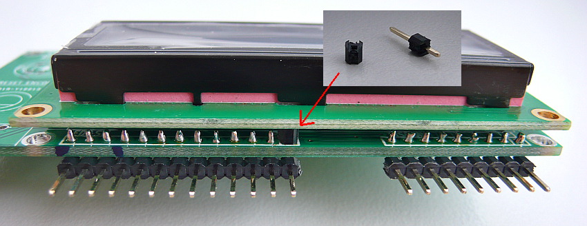
❏ Insulating spacer washers between LCD and PCB
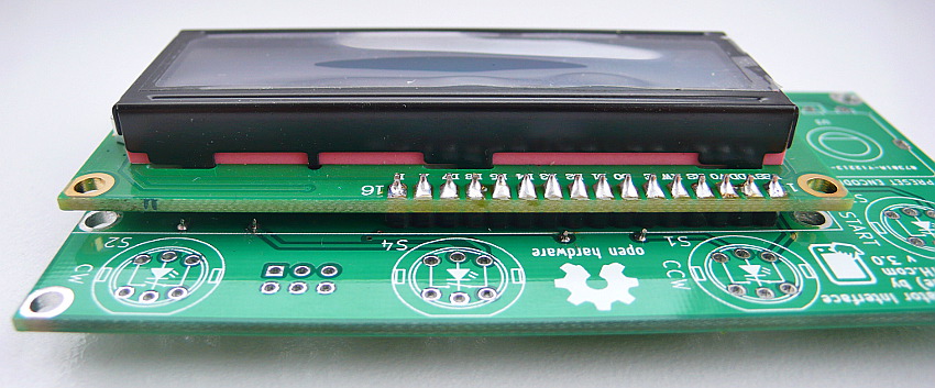
❏ LCD module to PCB
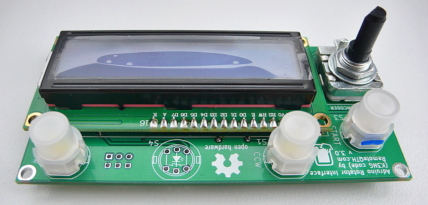
❏ CW, CCW and START switch (marked in blue) and preset encoder, Now front panel is final
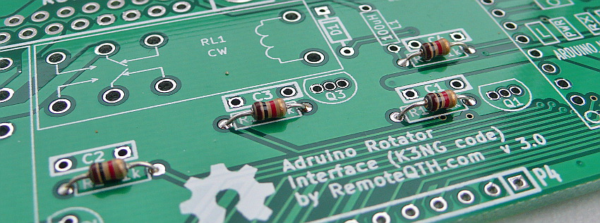
❏ Next R1 R2 R3 R5 (marked in black) solder on main board
❏ D1 D2 D3 D4 (marked in red)
❏ L1 L2 (marked in green)
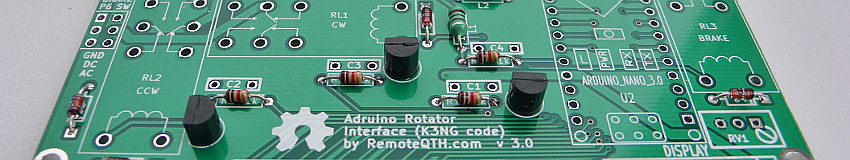
❏ Q1 Q2 Q3
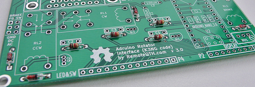
❏ C1 C2 C3 C4 and C5 between C4 and L1
❏ 6 pins of brake sw, Inputs connector, R9, DIL cocketfor Arduino NANO
❏ F15 connector, three relay, Arduino nano
❏ last solder front panel via pin strip