Remote multi rotator control
This revision is from 2014/01/13 14:43. You can Restore it.
- How to assemble the rack
- Rotators module
Version 2.0(Edit)

Examples(Edit)
- CDE 24V~ AC
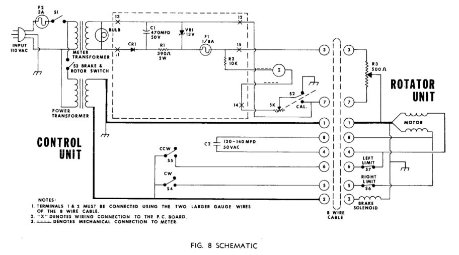
wire - description              - connected to
------------------------------------------------------------
1    - to GND
2    - Brake                    - pin 13 (DB15)
3    - resistor 500 ohm         - pin 14 through resistance (200 ohm) at pin 15 (DB15)
4    - capacitor                - C2
5    - CW                       - pin 7 + 8 (DB15)
6    - CCW                      - pin 3 + 4 (DB15)
7    - resistor                 - GND
8    - capacitor                - C2
------------------------------------------------------------
AC power for motor connected to PCB see image above, and pin 11+2 for brake
arduino pins connected(Edit)
| rotator azimuth | A7 |
| CW | D6 |
| CCW | D7 |
| CW switch | A5 |
| CCW switch | A4 |
| Brake | D8 |
| Start switch | A3 |
| CW encoder | D10 |
| CCW encoder | D9 |
| LCD | 2,3,4,5,11,12 |
| Free/unused | |
| SW1 | A0 |
| LED SW1 | D13 |
| SW2 | A6 |
| SW3 | A2 |
| SW4 | A1 |